| | LRK Home | | Bio Info | | Krash Khronicles | | LAROKE | |
| | BettyLou | | BillyBob's Garage | | Rat Patrol | | Deerslayer | | Elvira | |
| | Land of the Free and Home of the Brave | |
| | Keppylou's Art | | WWI Soldier's Diary | |
BillyBob Work-in-Progress Log
![]()
TRUCK LINKS including vendor sites for old parts, custom parts, and tools as well as sites for classic car and truck organizations
STORE Operating in association with Amazon.com, books, recordings and tools can be purchased.
PLANNING for the restoration including project schedule and cost estimates.
![]()
WORK-IN-PROGRESS is the restoration of parts of BillyBob that I can accomplish without a garage.
PRE-RESTORATION includes log entries of minor repairs and and adventures between time of purchase and the time when I started restoration, a piece at a time.
JR'S KORNER JR's Korner is the history of BillyBob before I got him authored by my brother, Wm. C. Kephart.
![]()
BILLYBOB MAINTENANCE Ever changing detailing, oil change, lube, etc. maintenance routines specifically developed for BillyBob, including required tools, materials and procedures.
![]()
You will need the Adobe Acrobat browser plugin to view these wiring diagrams which are in the PDF file format. This format allows zooming and panning. If you don't have this plugin, it can be downloaded and installed (free) from the Adobe site. The button below will take you there.
![]()
GAUGE LAMP CIRCUIT Gauge lamps connect to the rheostat connector on the headlamp switch. The lampholder above the ignition switch is non-functional for BillyBob's non-stock ignition switch.
HEADLIGHT CIRCUIT The headlight circuit diagram includes the headlight stub harnesses from the inner fender terminal blocks to the headlamps which haven't been installed yet.
CHARGING/IGNITION CIRCUIT The charging and ignition circuit includes the modifications I had to make to adapt the 12 volt regulator to the one-wire alternator harness.
TURN SIGNAL/BRAKE CIRCUIT The turn signal and brake light circuits show the changes made to accomodate the new wires provided in the main harness.
PARKING LIGHT/TAIL LIGHT CIRCUITS The tail light circuit includes the license plate light.
HORN CIRCUIT The horn circuit does not show the horns (beyond the terminal block) or the horn button (in the steering column) neither of which have been re-wired at this time.
GAS GAUGE CIRCUIT The gas gauge circuit does not show the sender unit which hasn't been replaced or re-wired yet.
BILLYBOB WIRING DIAGRAM Here's the whole spaghetti bowl. The present state of BillyBob's wiring diagram including all of the above sub-diagrams.
13. Nervous breakdown: It's Alive!
August 11th 2001 I'm still havin' trouble with the starter. Sometimes, it will spin and clatter and not engage. I think I've narrowed the problem down to the bendix or a worn ring gear. Since I didn't have this problem with the old starter, my bets are on the bendix. First thing this morning, I put the old starter back in BillyBob . . . We'll run this way for awhile to see if I'm right.
October 27th 2001 I haven't had any starter clatter since I put the old starter back in 'cept for one time. I had stopped at a gas station and when I turned the truck off, it "dieseled" for a few revolutions (not so fond memories of the seventies). When I started it after getting gas, the starter clattered. Might just be the ring gear after all.
BillyBob is laid up in his warehouse bay with a flat tire so I decided to work on the wiring today. The Thanksgiving Day weekend is coming up and and I'll have four days in a row to work on BillyBob . . . I think I've mustered enuf courage to tackle the installation of the wiring harness. I've started sleuthing my way thru the wiring harness connectors using the limited instructions that came with the harness, the 1954 Chevrolet Truck Wiring Diagrams For Complete Chassis booklet, and the Factory Assembly Manual. I also have a wiring diagram created by Chief, a member of the Stovebolt.com forums and a 1972 Chevrolet Truck wiring diagram to help me complete my wiring diagram that I started when I replaced the turn signals.
 After
puzzling over the single page instructions for the
wiring harness, several problems were discovered . . . first, not all
the connectors listed on the left side of the page have corresponding
marks on the harness diagram. Second, the list and diagram have
connector designations that are underlined, boxed, circled or plain but
the markers on the actual harness are just plain numbers thru-out and
many numbers are repeated. Finally, after playing around with the
multi-meter, checking for continuity, I've discovered that a wire
entering the wiring harness at one point is not always the same color
or number designation when it emerges at the other end! This is gonna
be fun - Keep that fire extinguisher handy! As I isolated the circuits
I began to make the harness connections to the converted twelve volt
instrument clusters I purchased some time back.
After
puzzling over the single page instructions for the
wiring harness, several problems were discovered . . . first, not all
the connectors listed on the left side of the page have corresponding
marks on the harness diagram. Second, the list and diagram have
connector designations that are underlined, boxed, circled or plain but
the markers on the actual harness are just plain numbers thru-out and
many numbers are repeated. Finally, after playing around with the
multi-meter, checking for continuity, I've discovered that a wire
entering the wiring harness at one point is not always the same color
or number designation when it emerges at the other end! This is gonna
be fun - Keep that fire extinguisher handy! As I isolated the circuits
I began to make the harness connections to the converted twelve volt
instrument clusters I purchased some time back.
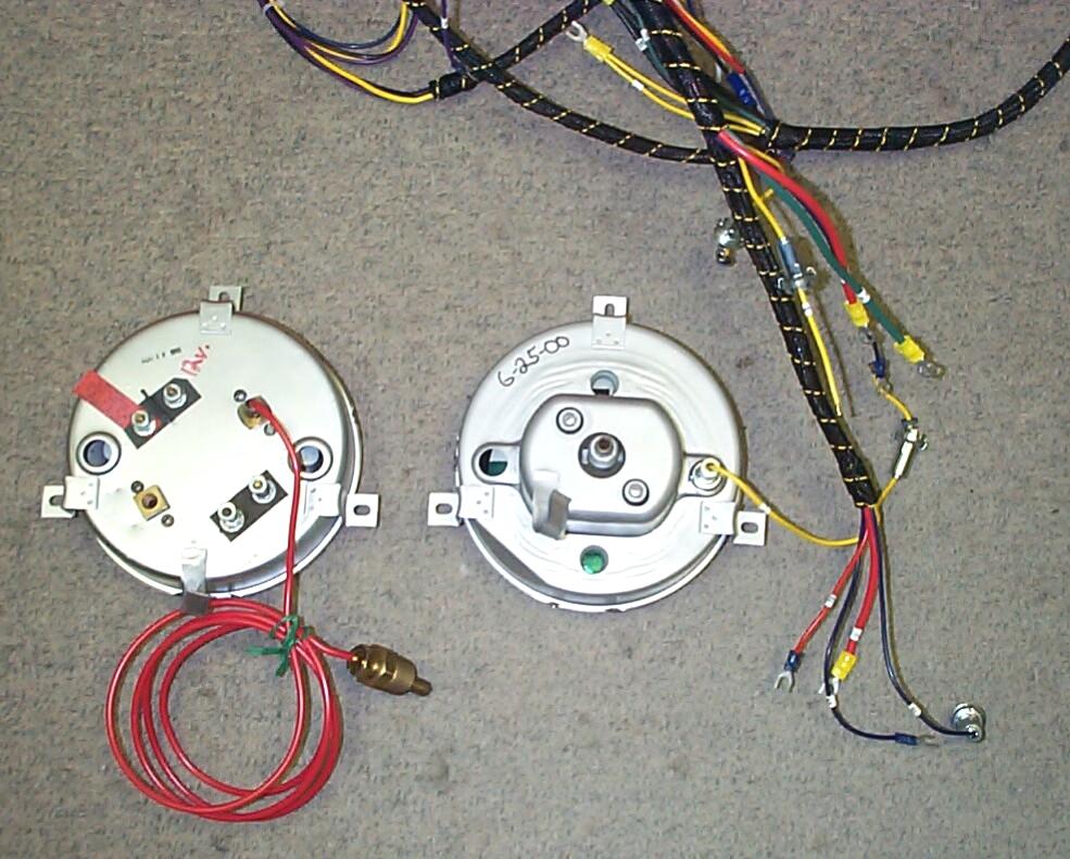
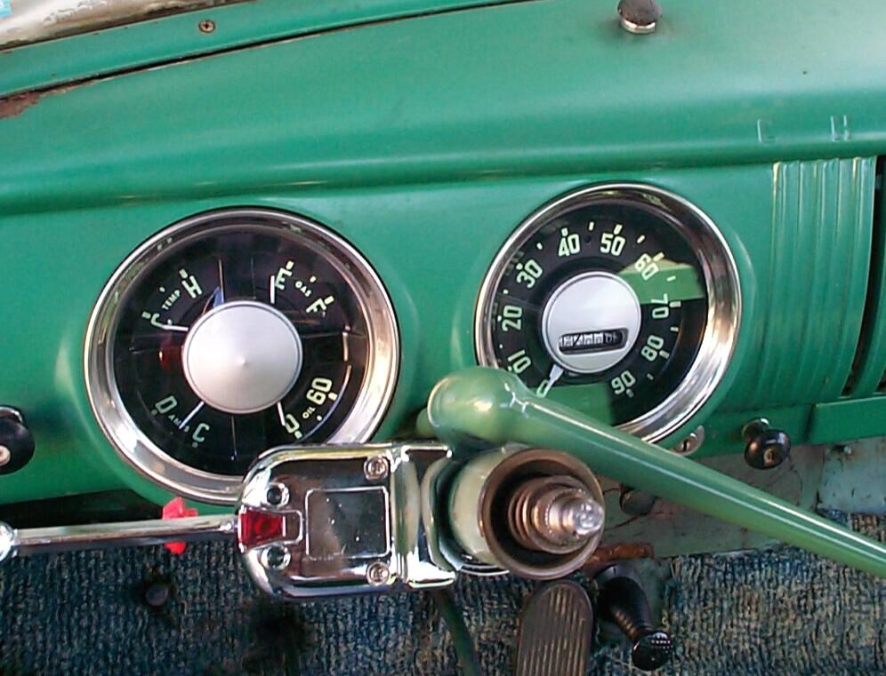
My head started to hurt, so I took a break and ran off to a couple of FLAPS (Friendly Local Auto Parts Store) to hunt for instrument cluster lamp bulbs. The original six-volt bulbs are designated as #55 rated at 2 candlepower. Took a guess and purchased a couple of #1895 12-volt bulbs to try out. Also picked up some permatex dielectric grease for future assembly. Back at the Krash Lab, the bulbs fit the sockets OK but I had my daily stupid attack by inserting the bulb holder into the opening for the hi-beam indicator light and breaking the lamp 'cause it was bigger than the space I was trying to force it into. The first circuit I straightened out and added to the wiring diagram was the gauge lamp circuit.
October 28th 2001 Continued today with the headlamp circuit up to the front fender terminal blocks. Over the next two weeks, I tracked down every circuit and added them to the main diagram. All these are listed in the panel on the left. They are in Adobe Acrobat PDF file format so they can be panned and zoomed.
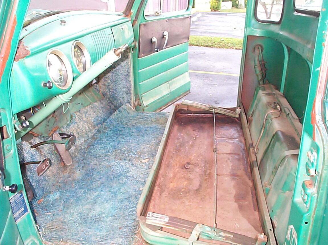 November
22nd 2001 Thanksgiving
and re-wiring D-day. I am thankful for great weather to work in. First
task (after disconnecting the battery) is to remove the ignition switch
which is not stock . . . That turned out to be easy, just a knurled
surround to unscrew, no secret buttons or releases to puzzle over. The
next job was to remove the steering wheel, turn signal director, shift
lever assembly and seat to provide elbow room. I'd never taken out the
seat before but it only took a few minutes (four hex nuts and a spring
to disconnect). A little awkward for one person but manageable. I
realized this thing would be a lot easier to re-install if I also
removed the sheetmetal "skirts" at each side, so I did that too (five
sheetmetal screws each).
November
22nd 2001 Thanksgiving
and re-wiring D-day. I am thankful for great weather to work in. First
task (after disconnecting the battery) is to remove the ignition switch
which is not stock . . . That turned out to be easy, just a knurled
surround to unscrew, no secret buttons or releases to puzzle over. The
next job was to remove the steering wheel, turn signal director, shift
lever assembly and seat to provide elbow room. I'd never taken out the
seat before but it only took a few minutes (four hex nuts and a spring
to disconnect). A little awkward for one person but manageable. I
realized this thing would be a lot easier to re-install if I also
removed the sheetmetal "skirts" at each side, so I did that too (five
sheetmetal screws each).
 Managed
to cuss my way thru disconnecting the existing gauge clusters from the
dashboard. I cut the wires to the gauge clusters, then disconnected the
oil pressure tube and speedometer cable. The speedo cable, oil pressure
line and water temp capillary tube all thread thru the same hole in the
firewall. When I first purchased the converted 12 volt gauge clusters I
thought the capillary tube to engine connector was too big to fit the
235 engine. I discovered later that it had a V8 adapter on it which
just screwed off. The firewall opening had no grommet and too many
existing objects passing thru it. I cut the old wires passing thru
(most of which were going to and from the voltage reducer) and
disconnected the wiper motor vacuum hose which also went thru here. The
wires passing thru here included a cold weather starting switch that JR
had hooked up to bypass the ballast resistor and shoot 12 volts to the
old 6 volt coil. I don't need that in South Florida so it was removed
completely.
Managed
to cuss my way thru disconnecting the existing gauge clusters from the
dashboard. I cut the wires to the gauge clusters, then disconnected the
oil pressure tube and speedometer cable. The speedo cable, oil pressure
line and water temp capillary tube all thread thru the same hole in the
firewall. When I first purchased the converted 12 volt gauge clusters I
thought the capillary tube to engine connector was too big to fit the
235 engine. I discovered later that it had a V8 adapter on it which
just screwed off. The firewall opening had no grommet and too many
existing objects passing thru it. I cut the old wires passing thru
(most of which were going to and from the voltage reducer) and
disconnected the wiper motor vacuum hose which also went thru here. The
wires passing thru here included a cold weather starting switch that JR
had hooked up to bypass the ballast resistor and shoot 12 volts to the
old 6 volt coil. I don't need that in South Florida so it was removed
completely.
 About
half past ten in the morning I severed the main harness at the firewall
and crossed the rubicon. There was no going back now. Cut the wires off
the existing gauges and ignition switch to get them out. cut all the
wires off the light switch except the dome light wire and the power
wire for the turn signal flasher. Removed the voltage reducer, old 6
volt voltage regulator, horn relay and fuse box from the firewall. Also
removed the secondary wiring harness going to the starter hot lead and
the ballast resistor (coil). Cleaned the firewall in this area with Eastwood's
"Under Gone" Undercoating/Heavy Residue Remover (#31130Z) and
Industrual Cleaner/Degreaser (#31131Z).
About
half past ten in the morning I severed the main harness at the firewall
and crossed the rubicon. There was no going back now. Cut the wires off
the existing gauges and ignition switch to get them out. cut all the
wires off the light switch except the dome light wire and the power
wire for the turn signal flasher. Removed the voltage reducer, old 6
volt voltage regulator, horn relay and fuse box from the firewall. Also
removed the secondary wiring harness going to the starter hot lead and
the ballast resistor (coil). Cleaned the firewall in this area with Eastwood's
"Under Gone" Undercoating/Heavy Residue Remover (#31130Z) and
Industrual Cleaner/Degreaser (#31131Z).
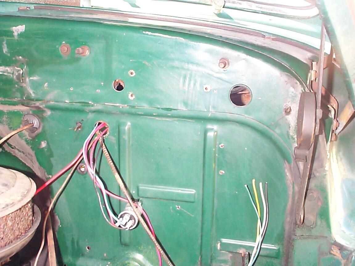
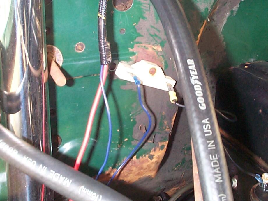 The
hole where the speedo cable, oil pressure line and water temp capillary
tube passes thru the firewall gets a "four wire" grommet. Why a four
hole grommet for three items? Beats me. I used this anomaly to my own
advantage by using the fourth hole for the the three turn signal
flasher wires. This left the hole thru the firewall intended for the
wiper vacuum line free for its original purpose. I couldn't figure how
to stretch the four wire grommet enuf to get all the items thru it, so
slits were cut to each of the four holes with the Dremel motor tool.
Next, the new secondary wiring harness from the starter hot lead and
the coil (ballast resistor) was installed along with its grommet. This
darn harness has three wires, but for the life of me, I can't figure
out what the third wire is for. After much trepidation, I cut the ends
off the unused wire where it enters the harness at each end. I put a
new spade connector on the coil wire to fit the ballast resistor
connector, in lieu of the ring connector the wire came with. The new
speedometer gauge cluster was installed and the speedo cable connected.
The
hole where the speedo cable, oil pressure line and water temp capillary
tube passes thru the firewall gets a "four wire" grommet. Why a four
hole grommet for three items? Beats me. I used this anomaly to my own
advantage by using the fourth hole for the the three turn signal
flasher wires. This left the hole thru the firewall intended for the
wiper vacuum line free for its original purpose. I couldn't figure how
to stretch the four wire grommet enuf to get all the items thru it, so
slits were cut to each of the four holes with the Dremel motor tool.
Next, the new secondary wiring harness from the starter hot lead and
the coil (ballast resistor) was installed along with its grommet. This
darn harness has three wires, but for the life of me, I can't figure
out what the third wire is for. After much trepidation, I cut the ends
off the unused wire where it enters the harness at each end. I put a
new spade connector on the coil wire to fit the ballast resistor
connector, in lieu of the ring connector the wire came with. The new
speedometer gauge cluster was installed and the speedo cable connected.
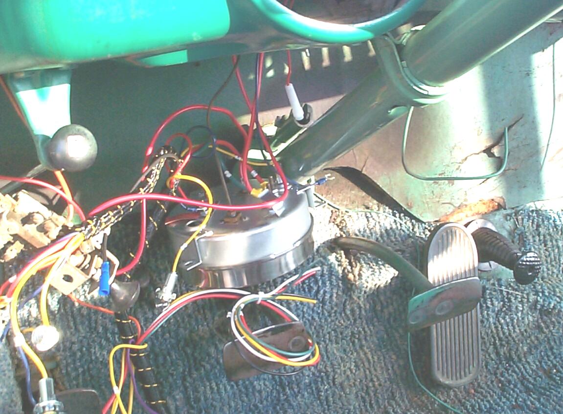 Installed
the ammeter, oil pressure, water temp, gas gauge cluster. OOPS!
There's a flag on the field . . . Five yards penalty for unnecessary
stupidity. It's next to impossible to tighten up all the gauge
connections when the cluster is in place. I had wisely planned to do
this task before placing the cluster, but for some reason I'd forgotten
in my rush to see the new instruments in place. I fiddled with trying
to tighten the connections with the cluster in place for awhile.
Finally, I took my medicine and removed the cluster again to do the job
right.
Installed
the ammeter, oil pressure, water temp, gas gauge cluster. OOPS!
There's a flag on the field . . . Five yards penalty for unnecessary
stupidity. It's next to impossible to tighten up all the gauge
connections when the cluster is in place. I had wisely planned to do
this task before placing the cluster, but for some reason I'd forgotten
in my rush to see the new instruments in place. I fiddled with trying
to tighten the connections with the cluster in place for awhile.
Finally, I took my medicine and removed the cluster again to do the job
right.
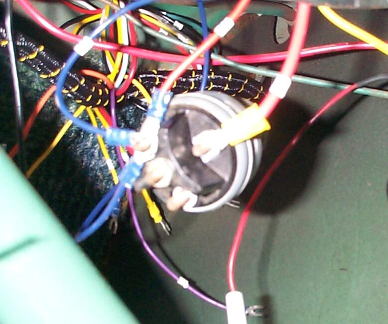 November
23rd 2001 Re-wiring
D-day plus one. The weather is terrific in the shadetree garage. I had
pre-wired the gauge clusters based on my wiring diagram studies. Today
I started by wiring and installing the ignition switch (of unknown
ancestry) based on those same studies. I would be in a whole mess of
confusion right now if I hadn't gone thru the motions of developing my
own wiring diagram. Before installing the ignition switch, I cleaned it
with Archer Cleaner/Degreaser for electronics I got at Radio Shack.
November
23rd 2001 Re-wiring
D-day plus one. The weather is terrific in the shadetree garage. I had
pre-wired the gauge clusters based on my wiring diagram studies. Today
I started by wiring and installing the ignition switch (of unknown
ancestry) based on those same studies. I would be in a whole mess of
confusion right now if I hadn't gone thru the motions of developing my
own wiring diagram. Before installing the ignition switch, I cleaned it
with Archer Cleaner/Degreaser for electronics I got at Radio Shack.
 Next,
the headlight switch was treated with the electonics cleaner, wired and
installed. A bullet connector was crimped to the existing horn wire
from the steering column. The shift lever linkage and turn signal
director were re-installed.
Next,
the headlight switch was treated with the electonics cleaner, wired and
installed. A bullet connector was crimped to the existing horn wire
from the steering column. The shift lever linkage and turn signal
director were re-installed.
 Turn
signal and brake switch wires from the new harness were cut to size and
crimped with bullet connectors. They were connected to the turn signal
director and the all loose wires were secured up under the dash with
wire ties to the dashboard supports. The dangling cigarette lighter
wire and heater blower wire were cut away. These two items will be
taken care of at some future date. I think I'm finished here (if I'm
lucky). Those new gauge clusters shure look good to me. Time to move to
the engine compartment.
Turn
signal and brake switch wires from the new harness were cut to size and
crimped with bullet connectors. They were connected to the turn signal
director and the all loose wires were secured up under the dash with
wire ties to the dashboard supports. The dangling cigarette lighter
wire and heater blower wire were cut away. These two items will be
taken care of at some future date. I think I'm finished here (if I'm
lucky). Those new gauge clusters shure look good to me. Time to move to
the engine compartment.
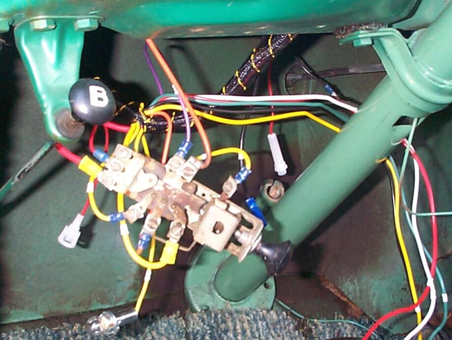
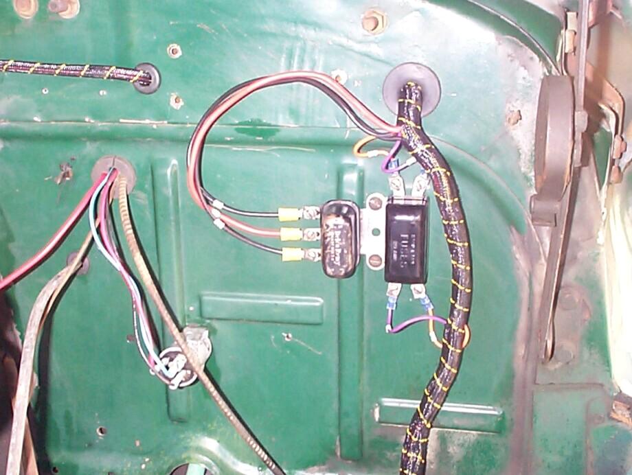 Spent
some time degreasing/cleaning the horn relay, fuse box and dimmer
switch. After the cleaning operations, the relay, box and switch were
re-installed and wired up. The brake light switch was also connected to
the new harness. Then I crawled underneath BillyBob to run the harness
to the taillight and gas gauge connections. Then I spent some time
getting dirt out of my eyes. The darn goggles were protecting my
forehead instead of my eyes!
Spent
some time degreasing/cleaning the horn relay, fuse box and dimmer
switch. After the cleaning operations, the relay, box and switch were
re-installed and wired up. The brake light switch was also connected to
the new harness. Then I crawled underneath BillyBob to run the harness
to the taillight and gas gauge connections. Then I spent some time
getting dirt out of my eyes. The darn goggles were protecting my
forehead instead of my eyes!
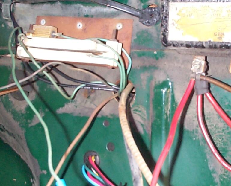
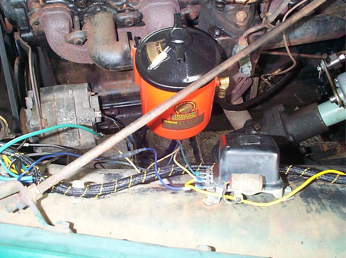 After
some headscratchin' and some reference book work I felt confident I'd
found a way to connect the existing 12 volt voltage regulator to the
"one wire" alternator wiring harness. I found a diagram
in Petersons "Basic Ignition and Electrical Systems", a Hot Rod
Magazine Technical Library book published in 1971 which I bought back
when I had pimples all over my face (well, more pimples anyway). I had
an alternator with three wires and a voltage regulator with four wires
just like in the diagram. The heavy wire from lug 1 of the alternator
matches with wire #3 from the new harness. The two existing wires from
the alternator to regulator were left in place. This left wire #24 from
the new harness which had a molded plug. I cut the plug off and saved
it. Downstream of this cut was a bulge in the wire like a snake
digesting a rat. I reasoned that this wire would be connected to the
"I" terminal of the regulator and that the bulge was a resistor to make
up for an "idiot light" that BillyBob does not possess. That left the
"A+" terminal on the regulator. The old wire connected to this terminal
had run to the "BAT" terminal on the old 6 volt regulator so I ran a
new wire from the A+ terminal to the hot terminal of the starter
switch. The alternator/regulator re-wiring finished, the only thing
left was to run the remainder of the harness out to the terminal blocks
on the inner fenders and parking light turn signals. There are stub
harnesses to the headlights that will be installed later when I replace
the headlight buckets.
After
some headscratchin' and some reference book work I felt confident I'd
found a way to connect the existing 12 volt voltage regulator to the
"one wire" alternator wiring harness. I found a diagram
in Petersons "Basic Ignition and Electrical Systems", a Hot Rod
Magazine Technical Library book published in 1971 which I bought back
when I had pimples all over my face (well, more pimples anyway). I had
an alternator with three wires and a voltage regulator with four wires
just like in the diagram. The heavy wire from lug 1 of the alternator
matches with wire #3 from the new harness. The two existing wires from
the alternator to regulator were left in place. This left wire #24 from
the new harness which had a molded plug. I cut the plug off and saved
it. Downstream of this cut was a bulge in the wire like a snake
digesting a rat. I reasoned that this wire would be connected to the
"I" terminal of the regulator and that the bulge was a resistor to make
up for an "idiot light" that BillyBob does not possess. That left the
"A+" terminal on the regulator. The old wire connected to this terminal
had run to the "BAT" terminal on the old 6 volt regulator so I ran a
new wire from the A+ terminal to the hot terminal of the starter
switch. The alternator/regulator re-wiring finished, the only thing
left was to run the remainder of the harness out to the terminal blocks
on the inner fenders and parking light turn signals. There are stub
harnesses to the headlights that will be installed later when I replace
the headlight buckets.
Time for the first test. Put the transmission in neutral, set the parking brake, dust off the fire extinguisher and connect the battery . . . No smoke, no bad smells. That's a promising sign. Next the engine was started . . . It did. That's the second good sign. OOPS! As hard as I tried to get it right, it appears I've wired the ammeter backwards. Second thing I noticed was the gas gauge. It pegs on full and stays there (the tank isn't full).
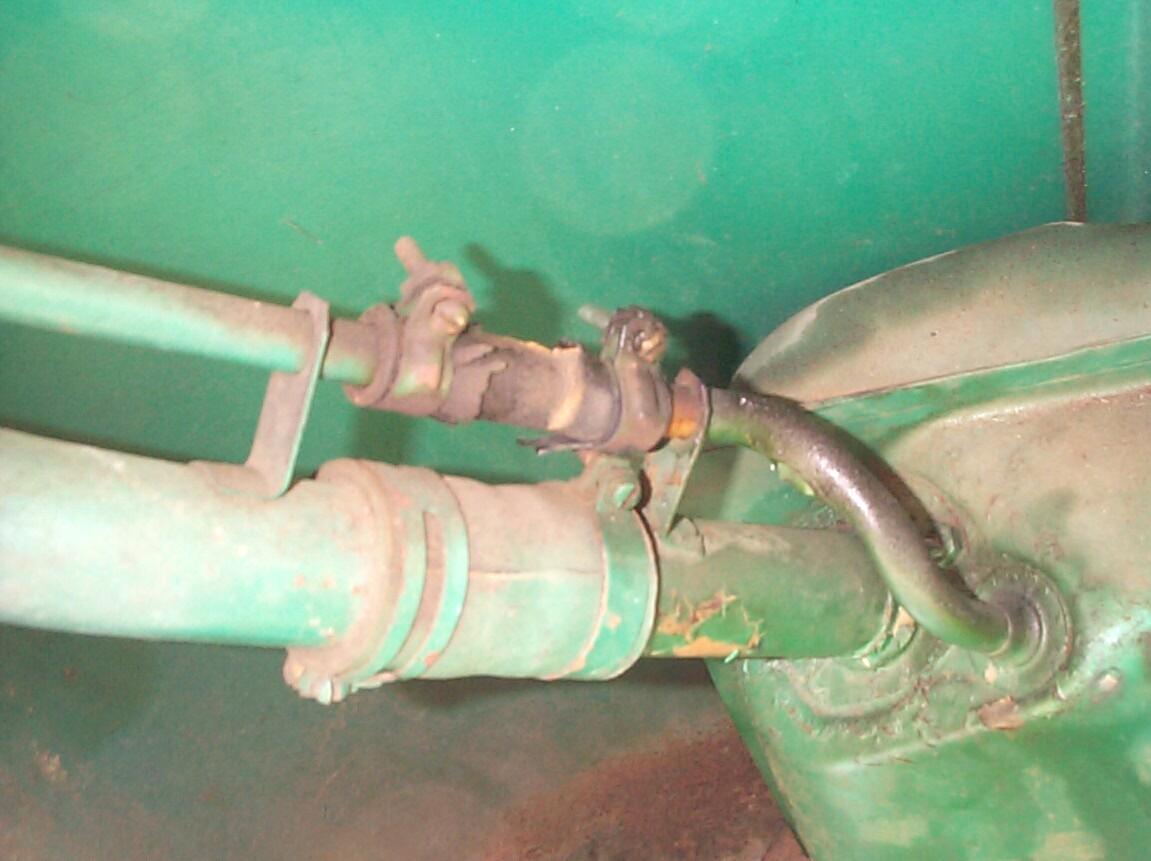 The
rest of BillyBob was reassembled with the idea in mind of "sea trials"
as soon as the sun sets so I can test the lighting. Before
re-installing the seat, I replaced the dry-rotted gas tank filler and
vent hoses. No gasket sealer was used as I believe I'll be removing the
gas tank in the near future.
The
rest of BillyBob was reassembled with the idea in mind of "sea trials"
as soon as the sun sets so I can test the lighting. Before
re-installing the seat, I replaced the dry-rotted gas tank filler and
vent hoses. No gasket sealer was used as I believe I'll be removing the
gas tank in the near future.
November 25th 2001 Re-wiring D-day plus three. The shakedown cruise went well. All the lights worked 'cept the hi-beam indicator. The speedometer/odometer is working. The old odometer reading was 77,316 miles and I'm sure It's rolled over at least once since BillyBob's engine has been rebuilt at least once. The new odometer is now at 31 miles. Oil pressure readings were the same as before. Water temperature readings were slightly lower and I'm wondering that since it had a V8 adapter, it might also be calibrated for higher temperatures. Last, but not least, the horns still produce a manly blast. On Saturday I made a FLAPS run and the hi-beam indicator lamp was replaced with a #1445 bulb which fixed that problem. I ordered a gas tank sender from Chevy Duty and will work on the gas gauge problem when it gets here. I will not be able to fix the ammeter problem without removing the switches and gauges again. I'll live with backwards readings until I'm ready to repaint the dashboard. I'm tired of bumping my head right now.
I had alloted four days for this task and I was essentially finished in two so, I used the additional time to flesh out this log entry and get it posted sooner. I think I had the spirit of my Dad who was an electronics guy riding shotgun with me on this job. My regular co-pilot, Murphy, was nowhere to be found. Installation of the main wiring harness and gauges takes BillyBob over the hump as far as electrical systems are concerned. There are still device replacements down the road (gas tank sender, ignition switch, headlight buckets, etc.) and loose ends to tie up . . . OUCH! sorry 'bout that.
| < Back
to Intro |
You can email me at ![]() webmaster@laroke.com
webmaster@laroke.com
Issued Sunday November 25, 2001
Updated Monday May 22, 2017
copyright © 1996-2017 Larry Robert Kephart all rights reserved
| | LRK Home | | Bio Info | | Krash Khronicles | | LAROKE | |
| | BettyLou | | BillyBob's Garage | | Rat Patrol | | Deerslayer | | Elvira | |
| | Land of the Free and Home of the Brave | |
| | Keppylou's Art | | WWI Soldier's Diary | |