|


STEP 2: CRIMP PIN
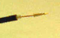 Fit the center pin from the connector package over the center conductor as far as it will go. The resulting length of exposed center conductor is the amount of conductor that will have to be cut off for a proper fit. Take the pin back off and cut the center conductor to the correct length with side cutter pliers. It should be 3/16 inch plus or minus. Now when the pin is placed back on the conductor, its base should just reach the inner insulation band (the center conductor should no longer be exposed.) Fit the center pin from the connector package over the center conductor as far as it will go. The resulting length of exposed center conductor is the amount of conductor that will have to be cut off for a proper fit. Take the pin back off and cut the center conductor to the correct length with side cutter pliers. It should be 3/16 inch plus or minus. Now when the pin is placed back on the conductor, its base should just reach the inner insulation band (the center conductor should no longer be exposed.)
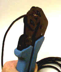 Place the pin on the center conductor, snug up the the crimping tool over the pin (in the special die portion of the crimper provided for the pin) . . . and when you're absolutely sure everything is properly aligned, crimp the pin to the center conductor. Be careful. If this is messed up, you have to start over preping the cable again with a new connector. Place the pin on the center conductor, snug up the the crimping tool over the pin (in the special die portion of the crimper provided for the pin) . . . and when you're absolutely sure everything is properly aligned, crimp the pin to the center conductor. Be careful. If this is messed up, you have to start over preping the cable again with a new connector.
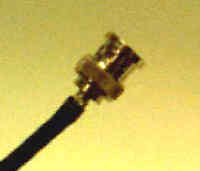
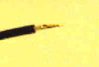 Here is the crimped pin - the base of the pin is seated on the top of the inner insulation band. The crimping process flattens out the pin a bit where the crimping tool applies pressure to it. Clean up any sharp edges left by the crimper with a jeweler's file, if necessary. Here is the crimped pin - the base of the pin is seated on the top of the inner insulation band. The crimping process flattens out the pin a bit where the crimping tool applies pressure to it. Clean up any sharp edges left by the crimper with a jeweler's file, if necessary.
STEP 3: INSTALL BNC CONNECTOR
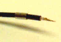 Slide the Crimp Barrel (or collar) over the cable before installing the connector itself - we will come back to the crimp barrel in the next step, but you have to slide it onto the cable now (you can't force it over the much larger connector later). Slide the Crimp Barrel (or collar) over the cable before installing the connector itself - we will come back to the crimp barrel in the next step, but you have to slide it onto the cable now (you can't force it over the much larger connector later).
 Now comes the real fun . . . NOT!! You must struggle with fitting the connector unto the cable. The knurled cylinder portion fits over the pin and inner insulation band and is press-fitted-twisted-cajoled-cursed into place. It has to fit snuggly between the outer and inner insulation bands, and during the process, it fights with the braided shielding for this tight space. Now comes the real fun . . . NOT!! You must struggle with fitting the connector unto the cable. The knurled cylinder portion fits over the pin and inner insulation band and is press-fitted-twisted-cajoled-cursed into place. It has to fit snuggly between the outer and inner insulation bands, and during the process, it fights with the braided shielding for this tight space.
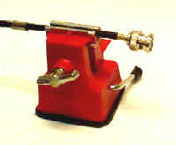
 A REAL Man or Grrrl can do this with their bare hands, but I use the hobby vise for more leverage and control. When you think you've got the connector jammed in under the insulation as far as it will go, jam it a little farther! You'll know you're finished when most of the knurled surface has disappeared under ithe insulation and the center pin is rigid in its seated location inside the connector. If the pin is loose and the connector is on as far as it will go, the length of exposed inner insulation band when the cable was stripped is too short. If the pin is tight but a lot of the knurled portion of the connector is still showing, the length of exposed inner insulation band and/or center conductor when the cable was prepared is too long. A REAL Man or Grrrl can do this with their bare hands, but I use the hobby vise for more leverage and control. When you think you've got the connector jammed in under the insulation as far as it will go, jam it a little farther! You'll know you're finished when most of the knurled surface has disappeared under ithe insulation and the center pin is rigid in its seated location inside the connector. If the pin is loose and the connector is on as far as it will go, the length of exposed inner insulation band when the cable was stripped is too short. If the pin is tight but a lot of the knurled portion of the connector is still showing, the length of exposed inner insulation band and/or center conductor when the cable was prepared is too long.
< Previous Page Next Page >
|